Getting Started
Ameba ARDUINO: Getting Started with BW16
Required Environment
BW16 Dual-Band Wi-Fi board currently supports Windows XP/7/8/10 32-bits and 64-bits operating systems. In this documentation, please use Arduino IDE with version 1.8.15 or later.
Introduction to BW16
Realtek RTL8720DN is a Wi-Fi and Bluetooth IC that supports 2.4GHz and 5GHz dual bands for Wi-Fi communication, and Bluetooth Low Energy (BLE) 5.0. BW16 is a module manufactured by B&T, this module is a highly integrated Wi-Fi and Bluetooth module with the RTL8720DN as the main SoC (System on Chip), it can be regarded as an SoC for the Wi-Fi and Bluetooth application with typical SBCs.
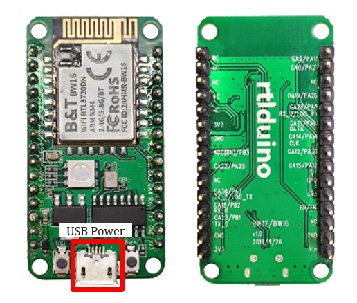
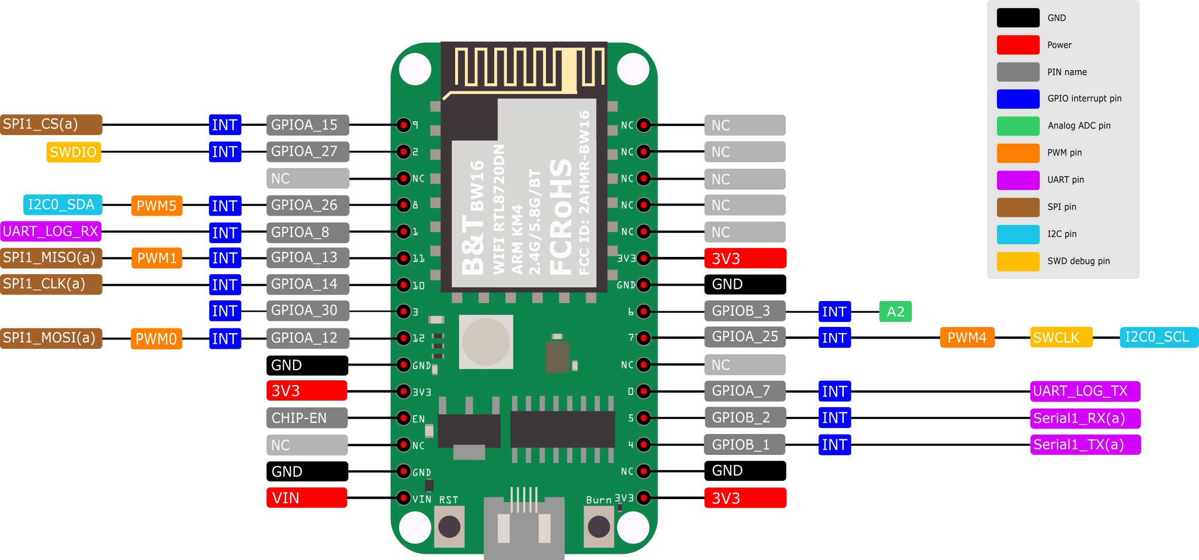
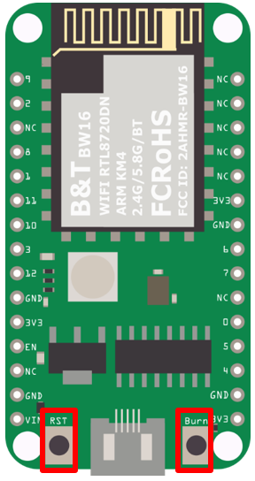
BW16 has a smaller size than AMB21 and AMB23 as shown in the above figure. It uses Micro USB to supply power, which is common in many smart devices. Please refer to the following figure and table for the pin diagram and function of BW16.
# |
PIN name |
GPIO |
ADC |
PWM |
UART |
SPI |
I2C |
|---|---|---|---|---|---|---|---|
D0(PA7) |
GPIOA_7 |
✓ |
UART_LOG_TX |
||||
D1(PA8) |
GPIOA_8 |
✓ |
UART_LOG_RX |
||||
D2(PA27) |
GPIOA_27 |
✓ |
|||||
D3(PA30) |
GPIOA_30 |
✓ |
|||||
D4(PB1) |
GPIOB_1 |
✓ |
Serial_TX |
||||
D5(PB2) |
GPIOB_2 |
✓ |
Serial_RX |
||||
D6(PB3) |
GPIOB_3 |
✓ |
A2 |
||||
D7(PA25) |
GPIOA_25 |
✓ |
I2C0_CLK |
||||
D8(PA26) |
GPIOA_26 |
✓ |
✓ |
I2C0_SDA |
|||
D9(PA15) |
GPIOA_15 |
✓ |
SPI_CS |
||||
D10(PA14) |
GPIOA_14 |
✓ |
SPI_CLK |
||||
D11(PA13) |
GPIOA_13 |
✓ |
✓ |
SPI_MISO |
|||
D12(PA12) |
GPIOA_12 |
✓ |
✓ |
SPI_MOSI |
Setting up Development Environment
Step 1. Installing the Driver
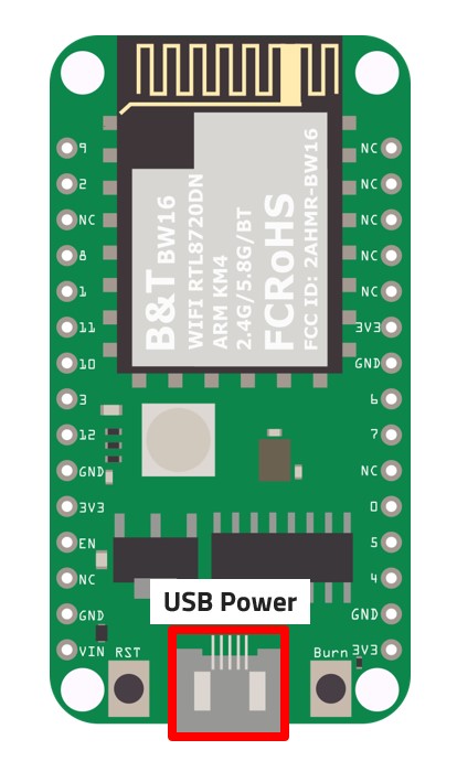
First, connect BW16 to the computer via Micro USB:
If this is the first time you connect BW16 to your computer, here is something that you might take note of:
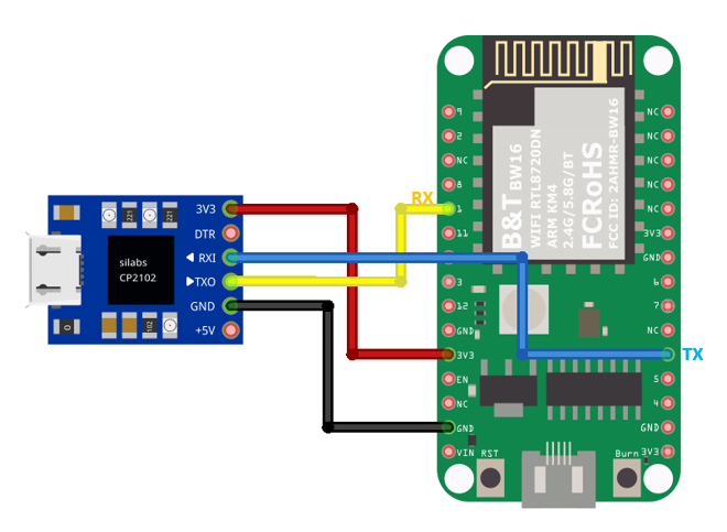
From the pinmap above, we know D0 and D1 pins are used for program uploading. However, according to the schematic design of AI Thinker, the onboard USB-to-UART module is connected to D4 and D5 which cannot be directly used for program upload. In order to upload firmware to this board, we suggested that you could choose to add in an external USB-to-UART module connecting to D0 and D1 as shown in the pin connection below:
Optionally, you could short the pins indicated below to use the on-board USB:
After connecting accordingly, the USB driver for BW16 will be automatically installed.
If you have driver issue of connecting board, please go to http://www.wch-ic.com/downloads/CH341SER_ZIP.html for USB driver.
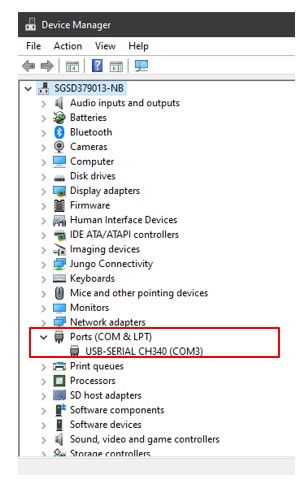
You can check the COM Port number in your Device Manager:
Step 2. Set up Arduino IDE
From version 1.6.5, Arduino IDE supports third-party hardware. TTherefore, we can use Arduino IDE to develop applications on BW16, and the basic examples of Arduino can run on BW16 too. Refer to the Basic Examples.
Arduino IDE can be downloaded in the Arduino website.
When the installation is finished, open Arduino IDE. To set up BW16 correctly in Arduino IDE, go to “File” -> “Preferences”.
And paste the following URL into “Additional Boards Manager URLs” field:
https://github.com/ambiot/ambd_arduino/raw/master/Arduino_package/package_realtek.com_amebad_index.json
BW16 will be supported from v3.0.8 officially.
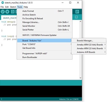
Next, go to “Tools” -> “Board” -> “Boards Manager”:
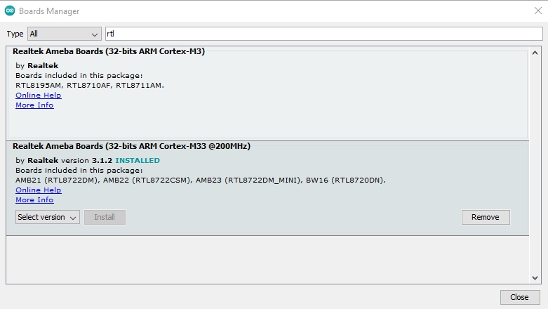
The “Boards Manager” requires about 10~20 seconds to refresh all hardware files (if the network is in bad condition, it may take longer). Every time the new hardware is connected, we need to reopen the Board Manager. So, we close the “Boards Manager”, and then open it again. Find “Realtek Ameba Boards (32-bits ARM Cortex-M33 @200MHz)” in the list, click “Install”, then the Arduino IDE starts to download required files for RTL8722DM.
If you are facing GitHub downloading issue, please refer to the following link at Download/Software Development Kit. There are 3 sections:
“AmebaD_Arduino_patch1_SDK”, please select at least 1 of the SDKs. There are 5 latest released SDK options.
“AmebaD_Arduino_patch2_Tools”, please select according to your operation system. There are Windows, Linux and MacOS.
“AmebaD_Arduino_Source_Code”, this section is optional download only wants to refer the latest source code.
Download the files selected, then unzip (patch1 and patch2 are compulsory). There are “Install.doc”/“Install.pdf” for you to refer installation steps. According to your system, please run the installation tool in the “Offline_SDK_installation_tool” folder.
After the installation tool running successfully, you may open Arduino IDE and proceed to “Tools” -> “Board“ -> “Boards Manager…”. Try to find “Realtek Ameba Boards (32-bits ARM Cortex-M33 @200MHz)”` in the list, click “Install”, then the Arduino IDE starts to download required files for AmebaD.
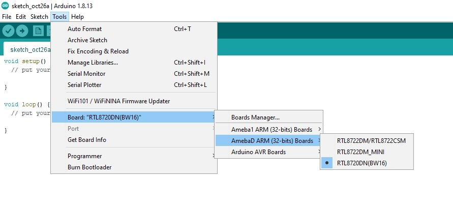
Finally, we select RTL8722DM as current connected board in “Tools” -> “Board” -> “Ameba ARM (32-bits) Boards” ->” RTL8722DM”:
How to upload firmware into BW16
Depending on the batch of manufacturing, some BW16 modules on the development board might have built-in the default B&T firmware, the firmware information is shown in the image below:
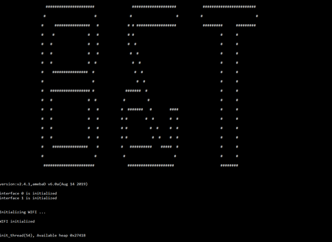
This will cause Arduino Image unable to flash into the module. Although information of “All images are sent successfully! Image tool closed! Upload Image did.” is showing in the Image Tool, however, the factory image is unable to be erased. Unfortunately after press the onboard RST button, you will find the factory image still remains in the flash.
Arduino IDE provides many built-in examples, which can be compiled, uploaded and run directly on the boards. Here, we take the “Blink” example as the first try.
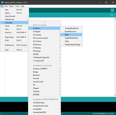
Open “File” -> “Examples” -> “01.Basics” -> “Blink”:
Uploading Solution
Method 1: Use AmebaD Image Tool to erase flash
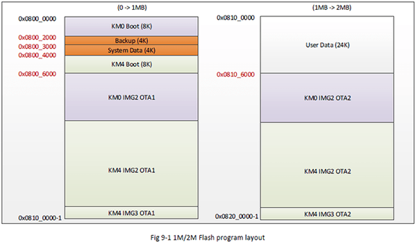
The B&T default factory image can be washed using “Erase” function provided by Realtek’s Image Tool. Using Image Tool to erase the flash image memory starting from memory address: 0x8000_0000 till the end of 2MB memory location, later on, we need to upload Realtek’s image back to the module again using Arduino IDE.
Step 1 – Download and prepare the Image Tool
Download ambd_sdk from the link ambiot GitHub: https://github.com/ambiot/ambd_sdk.
The Realtek’s Image Tool can be found under the following file path: “ambd_sdk\tools\AmbaD\Image_tool\image_tool.exe”
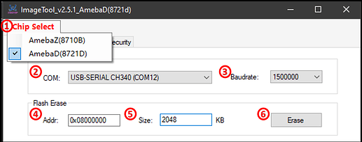
Step 2 – Setup the Image Tool
In the Chip Select option, choose AmebaD(8721D) which is also suitable for RTL8720DN chip.
Select correct COM Port that you are using.
Set the Baudrate to 115200.
Then key in the Flash Erase starting position from Memory Address of 0x0800 0000.
The size to be 2048 KB.
Set the module to “Download mode” first, then click the Erase button.
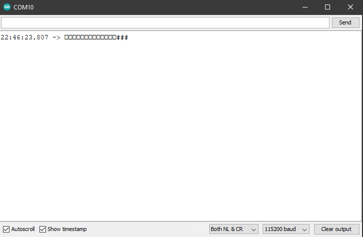
Upon finishing the above image erase and press the reset button, we could find that the
"#calibration" will no longer pop out, only "#" will appear in the Serial Monitor.
Step 3 – Download Image using Arduino IDE
Now you are able to download the program via UART in Ardunio IDE. In order to upload the program, you could choose to either use an external USB-to-UART module connecting to D0 and D1, or short the pins indicated below to use the on-board USB:
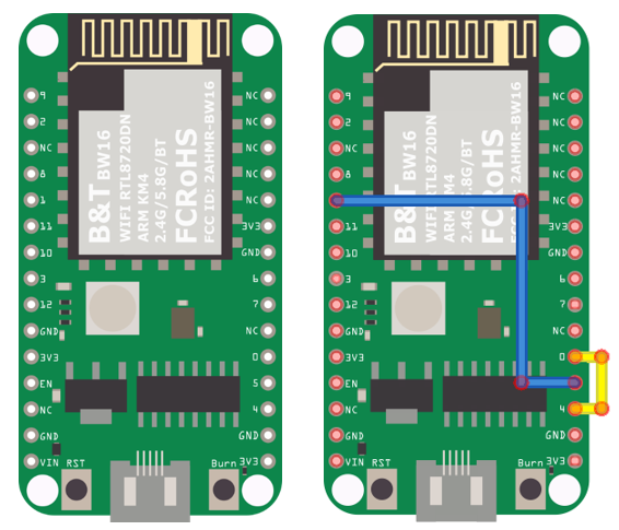
D1 ––– D5D0 ––– D4
Optional Uploading Solution
OTA (Over The Air)
Ai-Thinker is providing a guide for OTA firmware upload in Section 6.1 of B&T “RTL8720D AT Command User Manual” of which can be retrieved from this link here.
Try the First Example
Step 1. Compile & Upload
Arduino IDE provides many built-in examples, which can be compiled, uploaded, and run directly on the boards. Here, we take the “Blink” example as the first try.
Open “File” -> “Examples” -> “01.Basics” -> “Blink”:
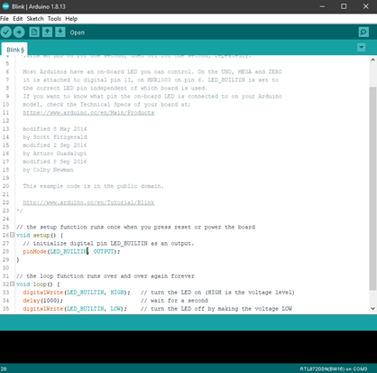
Arduino IDE opens a new window with the complete sample code.
Tip
There is two onboard LED on BW16, the default LED_BUILTIN is the onboard green LED.
Change LED_BUILTIN to LED_B or LED_R for different colors such as blue and red.
Here we use LED_B for demonstration purpose.
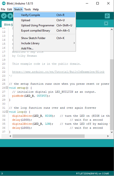
Next, we compile the sample code directly; click “Sketch” -> “Verify/Compile”
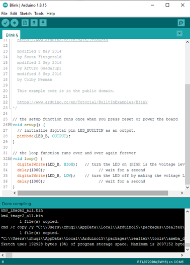
Arduino IDE prints the compiling messages in the bottom area of the IDE window. When the compilation is finished, you will get the message similar to the following figure:
Afterwards, we will upload the compiled code to BW16.
Please make sure BW16 is connected to your computer, then click “Sketch” -> “Upload”.
The Arduino IDE will compile first then upload. During the uploading process, users are required to enter the upload mode of the board. To enter the upload mode, first press and hold the BW16 Burn button, press the RST button, and then release the Burn button.
Please make sure the board is connected to your computer, then click “sketch” → “Upload”. There is a 5-seconds count down set as a reminder to enter the upload mode.
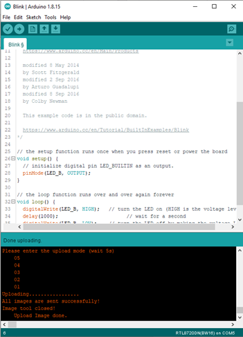
Again, during the uploading procedure the IDE prints messages. Uploading procedure takes considerably longer time (about 30 seconds to 1 minute). When upload completed, the “Done uploading” message is printed.
Step 2. Run the Blink example
In each example, Arduino not only provides sample code, but also detailed documentation, including wiring diagram, sample code explanation, technical details, …etc. These examples can be directly used on BW16.
So, we find the detailed information of the Blink example.
In short, for BW16, the example can be run on both the onboard RGB LED or external LED (use any GPIO pins for signal output). Finally, press the RST button, and you can see the RGB LED turns into blue and keep blinking.
References
Introduction of BW16 on Instructable: https://www.instructables.com/RTL8720DN/
Load Arduino image into BW16: How to load BW16 program with Arduino – #13
BW16 IMG2 SIGN Invalid Solution: RTL8720DN(BW16) IMG2 SIGN Invalid Solution
FTDI Driver Download from here: https://ftdichip.com/wp-content/uploads/2021/02/CDM21228_Setup.zip
(End)
Note
If you face any issue, please refer to the FAQ and Trouble shooting sections on Support page.