SPI – Print Image And Text On LCD Screen
If you are not familiar with SPI, please read Introduction to SPI first.
Preparation
AmebaD [AMB21 / AMB22 / AMB23 / BW16] x 1
ILI9341 TFT LCD with SPI interface x 1
Example
We have tested the following two models of ILI9341 TFT LCD with SPI interface:
Adafruit 2.8″ TFT LCD (with touch screen)
QVGA 2.2″ TFT LCD
Common pins in ILI9341 TFT LCD with SPI interface:
MOSI: Standard SPI Pin
MISO: Standard SPI Pin
SLK: Standard SPI Pin
CS: Standard SPI Pin
RESET: Used to reboot LCD.
D/C: Data/Command. When it is at Low, the signal transmitted are commands, otherwise the data transmitted are data.
LED (or BL): Adapt the screen backlight. Can be controlled by PWM or connected to VCC for 100% backlight.
VCC: Connected to 3V or 5V, depends on its spec.
GND: Connected to GND.
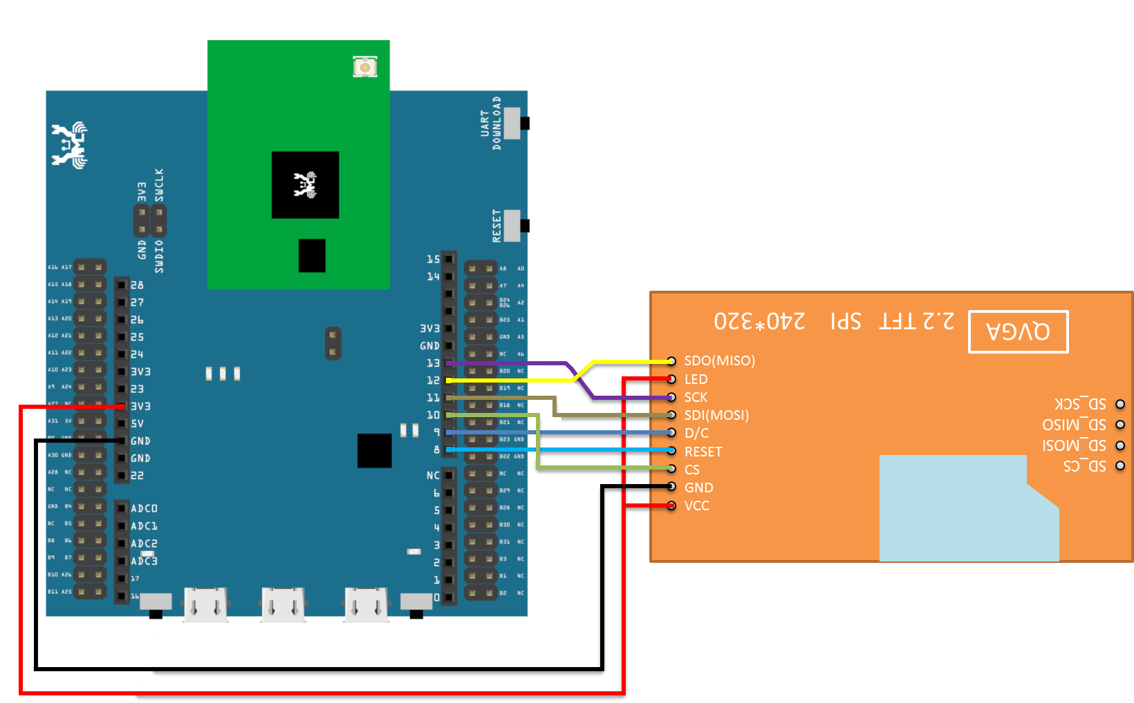
AMB21/ AMB22 and QVGA TFT LCD Wiring Diagram:
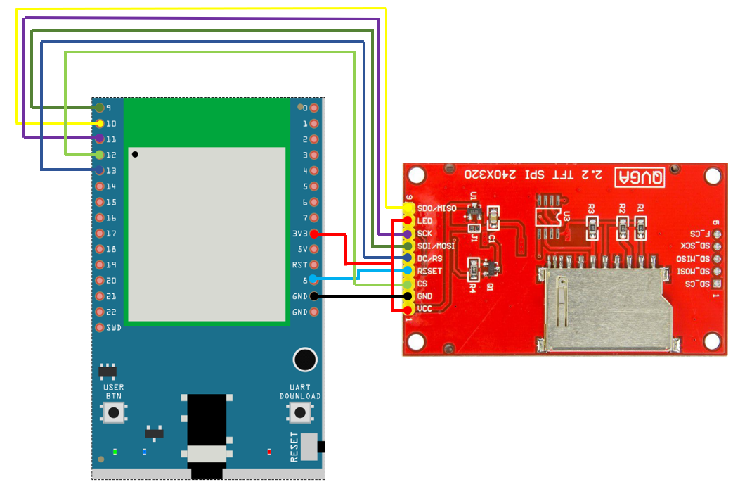
AMB23 and QVGA TFT LCD Wiring Diagram:
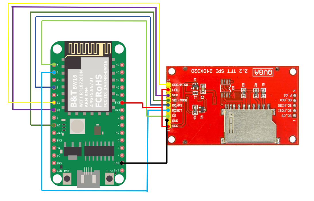
BW16 and QVGA TFT LCD Wiring Diagram:
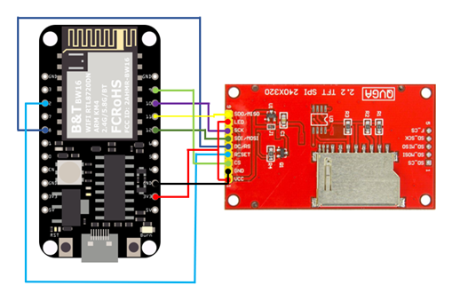
BW16-TypeC and QVGA TFT LCD Wiring Diagram:
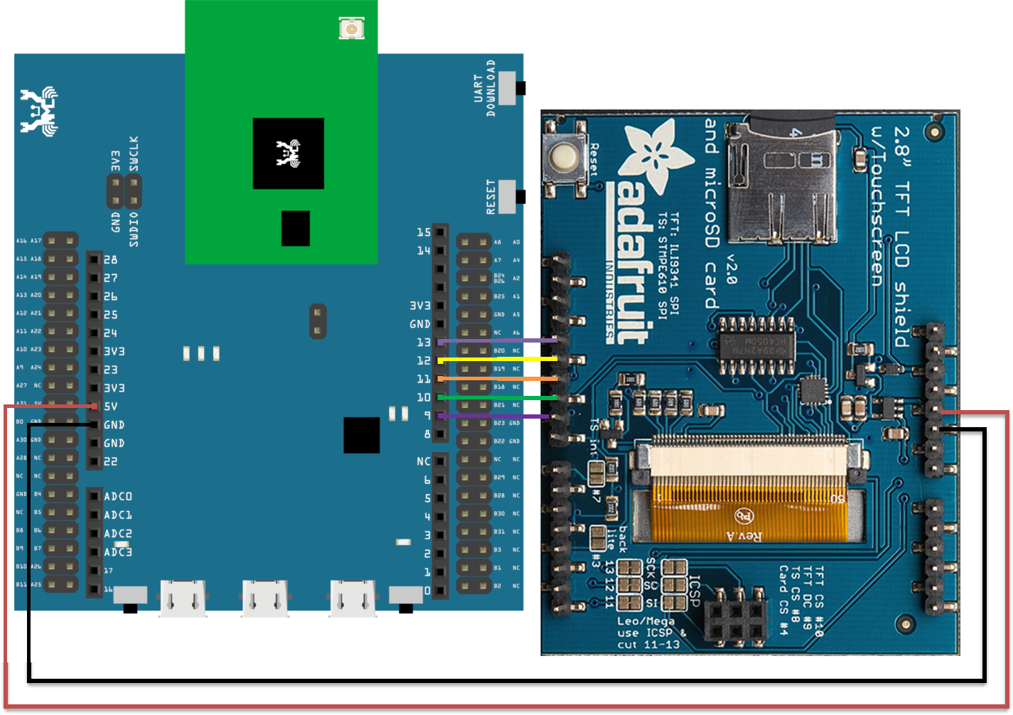
Wiring example of Adafruit 2.8” TFT LCD touch shield:
Note
this shield model enables the backlight by default and pin 8 is not for backlight, and the VCC should be connected to 5V.
AMB21 / AMB22 and Adafruit 2.8’’ TFT LCD touch shield Wiring Diagram:
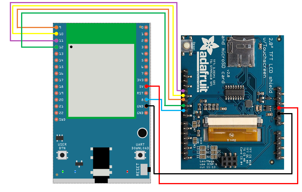
AMB23 and Adafruit 2.8’’ TFT LCD touch shield Wiring Diagram:
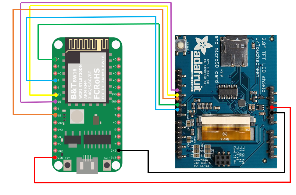
BW16 and Adafruit 2.8’’ TFT LCD touch shield Wiring Diagram:
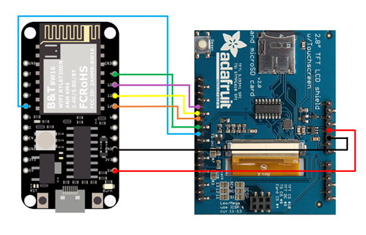
BW16-TypeC and Adafruit 2.8’’ TFT LCD touch shield Wiring Diagram:
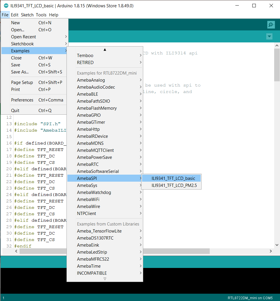
Open the example, “Files” → “Examples” → “AmebaSPI” → “ILI9341_TFT_LCD_basic”
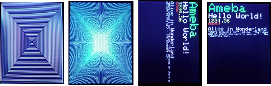
Compile and upload to Ameba, then press the reset button. Then you can see some display tests appear on the LCD screen, such as displaying different colors, drawing vertical and horizontal lines, drawing circles, etc.…
Code Reference
RGB 16-bit
ILI9341 uses RGB 16-bit to display colors. Different from RGB 24-bit, it uses 5 bits for red, 6 bits for green, 5 bits for blue. For example, the RGB 24-bit representation of sky blue is 0x87CEFF, that is in binary:
Red: 0x87 = B10000111
Green: 0xCE = B11001110
Blue: 0xFF = B11111111
and converted to RGB 16-bit:
Red: B10000
Green: B110011
Blue: B11111
Then concatenate them, which forms B1000011001111111 = 0x867F
Drawing of ILI9341
First you must specify the range of the rectangle to draw, then pass the 2-byte RGB 16-bit color to ILI9341 corresponding to each pixel one by one, in this way ILI9341 fills each color to each pixel.
You still must specify the drawing range even though the range covers only one pixel.
From the rules we mentioned above, we can conclude that drawing vertical or horizontal lines are faster than diagonal lines.
Printing text on ILI9341
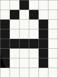
In our API, each character is 5×7 but each character is printed to size 6×8 (its right side and below are left blank), so as to separate from next character. For example, the character “A”:
The font size represents the dot size. For example, if the font size is 2, each dot in the character is a 2×2 rectangle
Screen rotation
ILI9341 provides 0, 90, 180, 270 degrees screen rotation.
If the original width is 240 and original height is 320, when the screen rotates 90 degrees, the width becomes 320 and the height becomes 240.