IR - Transmit IR NEC Raw Data And Decode
Materials
AmebaD [AMB21 / AMB22 / AMB23 / BW16 ] x 2
Grove – Infrared Emitter x1 (Figure 1)
Grove – Infrared Receiver x1 (Figure 2)
Example
In this example, we use two AmebaD to connect with an infrared (IR) Emitter and an IR Receiver separately to transmit and receive IR NEC Raw data.
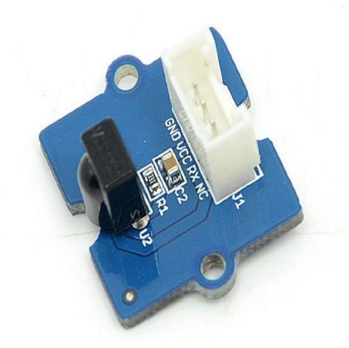
Figure 1: Grove – Infrared Receiver

Figure 2: Grove – Infrared Emitter
On the transmission side, the transmitter will send IR NEC raw data. The raw data can be seen as consecutive durations of “marks” and “spaces” (Figure 3) in microseconds (us).
Mark: a specific period of sending pulses
Space: a specific period of sending nothing
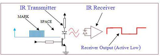
Figure 3: A typical IR transmission and reception setup implementation
For more details, please refer to SB-Projects’ topic of IR Remote Control Theory to learn the theory of IR remote controls operation and a collection of IR protocol descriptions. In this example, we are going to use NEC (Now Renesas, also known as Japanese Format) as the transmission protocol.
- NEC Features
8-bit address and 8-bit command length.
Extended mode available, doubling the address size.
Address and command are transmitted twice for reliability.
Pulse distance modulation.
The carrier frequency of 38kHz.
Bit time of 1.125ms or 2.25ms.
Modulation NEC protocol uses Pulse Distance Encoding of the bits for data communication (Figure 4). A logical “1” is represented by total duration of 2250us, with 560us of “marks” and (2250-560) us of “spaces”. While logical ”0” is represented by total duration of 1120us, with 560us “marks” and (1120-560) us of “spaces”.
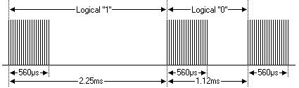
Figure 4: Modulation of NEC
Since a total number of 32-bit data together with the header and the end-bit will be transferred (Figure 5). If we separate the data in the time-frame (in us), there will be ( 2 + 32 ) x 2 + 1 = 69 “marks” / “spaces” to be transmitted (Figure 6), which forms the raw NEC data we would like to transmit in our Arduino “*.ino” file. This part of the code can be modified by users. Details of how to obtain raw data code for your remote devices, you may refer to Ken Shirriff’s blog, where it provides multiple libraries provided online.
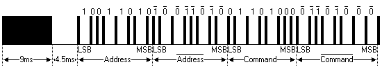
Figure 5: Sample of a Full NEC Data (in logic1 or 0)
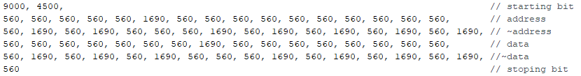
Figure 6: Sample of a Full NEC RAW Data (in us)
Figure 7 and 8 shows the pin configuration of IR Emitter and Receiver with AMB21/AMB22.
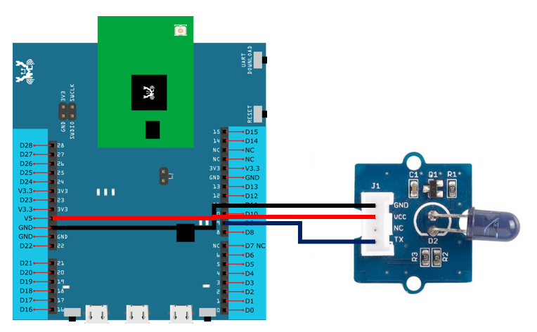
Figure 7: Pin configuration of IR Emitter and AMB21/AMB22
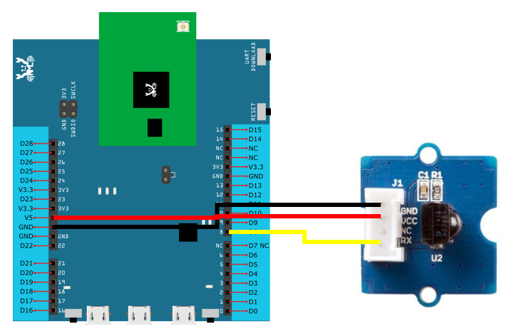
Figure 8: Pin configuration of the IR Receiver and AMB21/AMB22
Figure 9 and Figure 10 shows the pin configuration of IR Emitter and Receiver with BW16.
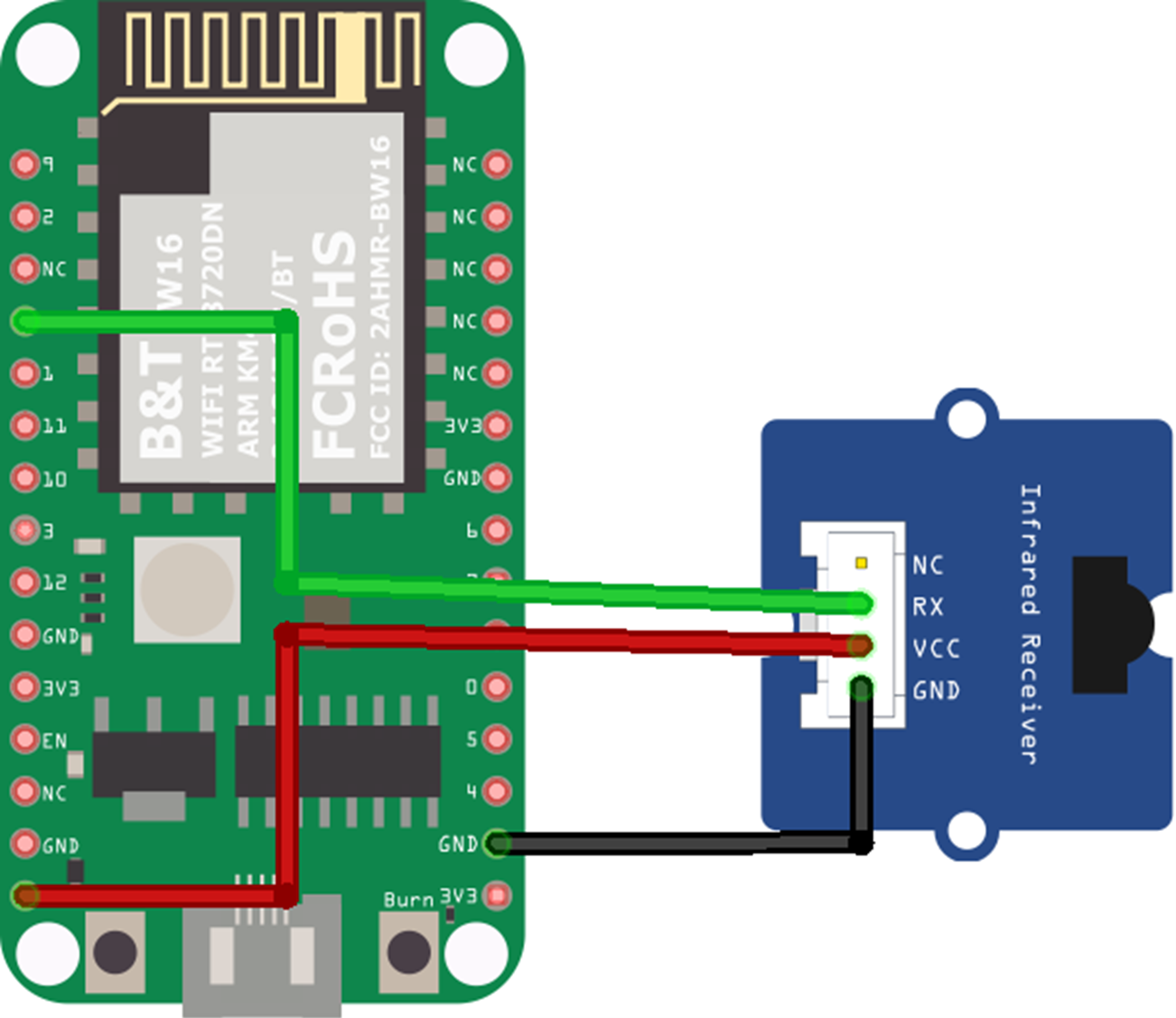
Figure 9: Pin configuration of IR Emitter and BW16
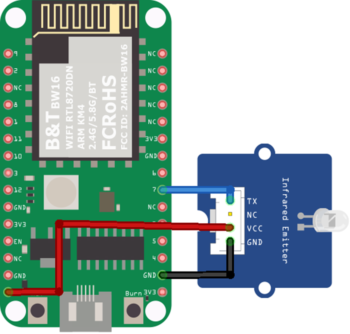
Figure 10: Pin configuration of IR Receiver and BW16-TypeC
Figure 11 and Figure 12 shows the pin configuration of IR Emitter and Receiver with BW16-TypeC.
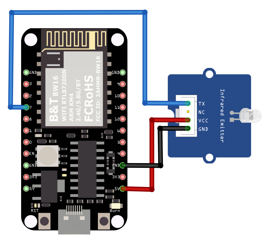
Figure 11: Pin configuration of IR Emitter and BW16-TypeC
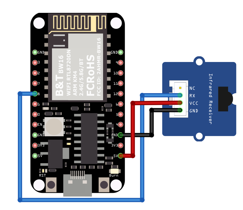
Figure 12: Pin configuration of IR Receiver and BW16-TypeC
After the connection is being set up correctly, we will move to the coding part for this example. First, make sure the correct Ameba development board is selected in Arduino IDE: “Tools” → “Board”.
Open the “IRSendRAW” example in “File” → “Examples” → “AmebaIRDevice”
→ “IRSendRAW” (Figure 13) and upload to 1st board connected with IR
Emitter:
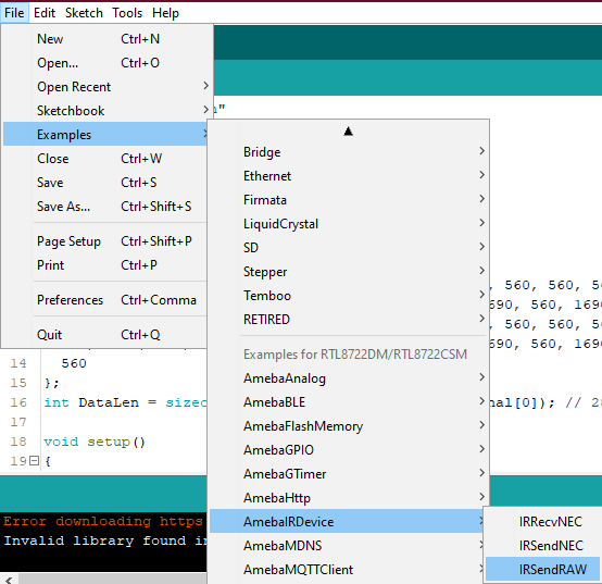
Figure 13: Example Location of IRSendRaw and IRRecvNEC
After successfully upload the sample code for IRSendRaw, you might need
to upload the IRRecvNEC example for the 2nd board connected with IR
Receiver from “File” → “Examples” → “AmebaIRDevice” → “IRRecvNEC”.
After opening the serial monitor on the IR Receiver side and press the reset buttons on two boards, the data “48” will be received every 3 seconds (due to the delays () function, not compulsory to wait). After decoding the signal from the receiving Pin D8 and transmitting Pin D9 with Logic Analyser and Pulse View (Figure 14), the result is also shown as “48” after decoding the receiving data with IR NEC Protocol.
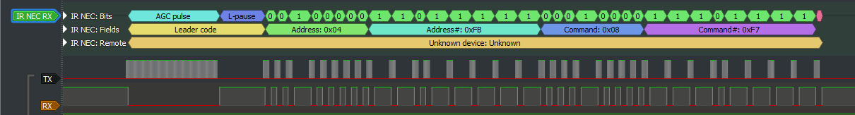
Figure 14: Pulse View results from sending and receiving pin
Code Reference
[1] Seeed Official website for Grove – Infrared Receiver https://wiki.seeedstudio.com/Grove-Infrared_Receiver/
[2] Seed Official website for Grove – Infrared Emitter https://wiki.seeedstudio.com/Grove-Infrared_Emitter/
[3] Ken SHirriff’s blog on A Multi-Protocol Infrared Remote Library for the Arduino http://www.righto.com/2009/08/multi-protocol-infrared-remote-library.html
[4] SB-Projects: IR Remote Control Project https://www.sbprojects.net/knowledge/ir/index.php